2.3 SYSTEMS ANALYSIS AND DESIGN LAYOUT
So far, numerous important basic considerations for rocket engine design have been discussed. The detailed engine design procedures and the treatment of typical examples as they may occur in practice will now follow. The questions are where to start, how to proceed, and what are the expected results.
It would be beyond the scope of this book to describe the detailed mechanics of the generation of design drawings, their breakdown, their execution, and the system for their release. The young engineer, who uses this book and already works in industry, knows. The student reader can be assured that the future employer has a manual (usually voluminous) covering this subject exhaustively, and which is slanted to his specific needs. The following are specific design techniques as they are used in liquid rocket engine design. Many of these techniques will be
LIQUID ROCKET ENGINE DESIGN CHECK-OFF SHEET
Project: Subsystem: Supervisor:
| Item | Answer & initials of designer | Date | Answer & initials of supervisor | Date |
|---|---|---|---|---|
| 1. Have designs for similar earlier projects been thoroughly reviewed and understood? | ||||
| 2. Have principal participants in those projects been contacted? Has their advice been solicited? | ||||
| 3. Has a list been prepared of all problems which were encountered in previous, related projects. including their solutions? | ||||
| 4. Has the new engine system schematic diagram been reviewed for hidden "won't works?" | ||||
| 5. Has the number of components and their complexity been reduced to a minimum, without loss in llexibility and serviceability, for maximum reliability? (In particular: has minimum of moving parts been achieved?) | ||||
| 6. Has a thorough malfunction analysis been made? (Assessment of malfunction effects of each component on all other parts and on the complete system. Include external systems, such as the vehicle and CSE.) | ||||
| 7. Have all existing detail designs been reviewed for possible inclusion and or adaptation to the new design? | ||||
| 8. Have standard parts been used wherever possible; permissible; or as ptescribed by customer specifications? | ||||
| 9. Has the number of external connections ("customer connections") been held to a minimum? | ||||
| 10. Has the location and type of customer connections been chosen in the best interest of the customer? | ||||
| 11. Has the need for ground support equipment (GSE) been reduced to a minimum, by number as well as by complexity? | ||||
| 12. Are there good reasons if support equipment used during R&D is different from the one supplied to the field? | ||||
| 13. Have all environmental conditions been considered, including those not likely but possible to occur? (Salt spray, sand, fungus, humidity, temperature, etc.) | ||||
| 14 Has resistance to vibration and shock effects been considered? In all planes? Including improper handling? | ||||
| 15. Have acceleration effects been considered? In all planes? |
LIQUID ROCKET ENGINE DESIGN CHECK-OFF SHEET-Continued
| Itern | Answer & initials of designer | Date | Answer & initials of supervisor | Date |
|---|---|---|---|---|
| 16. Has the use of critical materials been held to a minimum? (Chromium, Molybdenum, Tungsten, Cobalt, etc.?) | ||||
| 17. Has it been made absolutely certain that no cheaper materials will do? | ||||
| 18. Has it been assured that no electrolytic action can occur due to attachment of dissimilar metals? | ||||
| 19. Can the engines be gimbaled according to specifications? | ||||
| 20. Can the engine be clustered, if necessary? | ||||
| 21. Can the engine be attached to air frames other than the one presently contemplated? | ||||
| 22. Has it been confirmed that all parts can be made? | ||||
| 23. Has it been confirmed that there is no cheaper way of making these parts? | ||||
| 24. Can the parts readily be assembled, with a minimum of special tools? | ||||
| 25. Has it been made impossible to incorrectly assemble and install any part? (Or incorrectly reassemble and reinstall them in the field?) | ||||
| 26. Will all parts requiring service be readily accessible, prior to and following mating of the engine with the vehicle? | ||||
| 27. Have all markings been called out completely and correctly? | ||||
| 28. Do instructions for inspection and quality control leave no gap? | ||||
| 29. Has it been ascertained that (without penalty) the design cannot save further weight? | ||||
| 30. Is the envelope the smallest possible? | - | |||
| 31. Can the system be drained, readily and completely? (Avoidance of traps, low spots, etc.) | ||||
| 32. Have engine propellant feed system components, including pumps and thrust chamber been designed for minimum trapped propellants after cutoff? (Minimum wet weight) | ||||
| 33. Has the purchasing department been appraised of the significance of mandatory (proven) sources, where applicable? | ||||
| 34. Can it be transported? In one or several pieces? |
LIQUID ROCKET ENGINE DESIGN CHANGE CHECK-OFF SHEET
Project: Change No.: Supervisor:
| Item | Initials of designer | Date | Initials of supervisor | Date |
|---|
Assuming that it has been ascertained beyond doubt (has it?) that a design change must be made, check that the effect of this change is fully understood and implemented in the following areas:
- Interchangeability of changed parts.
- "Chain Reaction" to other parts and systems, including vehicle, test facilities, and GSE.
- Engine start and stop sequence.
- Engine performance. including gain factors.
- Conformance with all specifications.
- Weight, envelope, c.g.. moments of inertia, loads
- Reliability.
- Instrumentation, data recording, telemetry.
- Packaging, shipping, storage
- Development and qualification.
- Human factors: skills, training, notification of persons concerned.
- Field service equipment and procedures.
- Handbooks and other user documents.
- Logistics (spate parts maintenance).
- Manufacturing tooling and processes.
- Purchased materials.
- Subcontractor-supplied parts.
- Funding.
- Agreed-to delivery dates.
- Customer notification and approval. applied in subsequent chapters, in connection with the discussion and demonstration of various component designs.
The activities discussed below are not clearly separated phases, following one another in a rigid sequence. Rather, they overlap, frequently occur in parallel, and are tightly interwoven. One of the first drawings the liquid-rocket designer will most likely prepare is a schematic diagram of the engine system. A typical example is shown in figure 2-10. This diagram shows how the principal components are linked together. The schematic may be accompanied by a sequence diagram, showing the operation of each compo- nent in relation to the other as a function of time (fig. 2-11).
Concurrently, analyses will have been conducted to establish preliminary engine performance parameters and operating characteristics, as well as individual component configurations and operating principles. A typical example of a performance diagram is shown in figure 3-1. Engine and component starting and operating characteristics can be analytically predicted with a high degree of accuracy by computers. Thus, important knowledge required for optimum design is obtained long before the part is actually built and tested. Savings in time and cost are
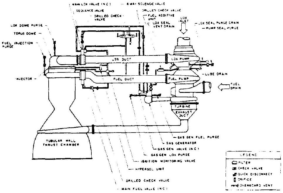 Figure 2-10.-Typical engine system schematic diagram.
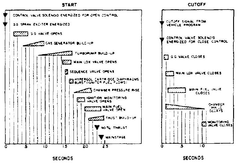 Figure 2-11.-Typical engine system sequence diagram.
substantial. These analyses and computer programs will draw heavily upon experience with earlier systems and on advanced design studies.
Once the prototype schematic diagram is considered completed, and performance parameters have been established by the analysis, the first actual "engine picture" will be drawn. This very likely will be a general, in-scale preliminary layout of the engine system and components. A typical example of an engine system preliminary layout is shown in figure 3-2.
Through continued analyses, calculations, consultations, and joint reviews by all participants, the layout will gradually take final shape. In this process, nothing should be left to chance.
Consultations with specialists in their fields and rigorous calculations doublechecked for accuracy and presented in a readily understood form, will contribute materially. Layout drawings should be made accurately and to true scale. In this manner, all components of the engine system will have been designed and optimized for one another, rather than "hung on a mounting frame in Christmas-tree fashion."
Before working drawings are made from the layouts, they should again be reviewed, and revised as necessary, taking into consideration all design aspects, the basic considerations, and the reliability assurance aspects, which were discussed earlier.